Equip-Link
Equip-Link
Equip-Link
Explore our primary physical interfaces, fiber transceiver modules, and EMI-shielded connector systems. Designed to deliver zero signal attenuation across high-density enterprise environments.
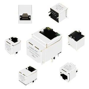 Waterproof Vertical Cat5e Cat6 Cat7 Data Socket Outlet Rj 45 Keystone Modular Jack Cat6a Rj45 Ethernet Sealed Connector
Inquire Now
Waterproof Vertical Cat5e Cat6 Cat7 Data Socket Outlet Rj 45 Keystone Modular Jack Cat6a Rj45 Ethernet Sealed Connector
Inquire Now
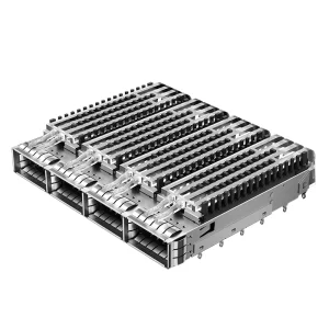
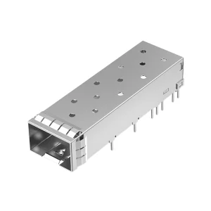
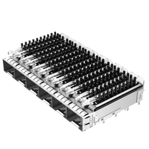 2198236-4 TE Replacement Through Hole 1x6 Ports Light Pipe Press-fit SFP+ Cage With Heatsink
Inquire Now
2198236-4 TE Replacement Through Hole 1x6 Ports Light Pipe Press-fit SFP+ Cage With Heatsink
Inquire Now
In modern network architecture, understanding the mechanical and signal characteristics of the physical layer is paramount. An Ethernet Splitter operates on a structural, non-switching principle. By utilising the copper layout of a standard Category 5e or Category 6 UTP cable, a passive splitter maps two independent physical connections over a single 8-pin structured cable.
Standard Fast Ethernet (100Base-TX) strictly utilizes pairs 2 (pins 1 and 2) and 3 (pins 3 and 6) for data transmission. This design leaves pairs 1 and 4 unused. An Ethernet splitter maps the secondary connection to these remaining wire lines (pins 4, 5, 7, and 8). When deployed in pairs at both ends of a structural run, they effectively compress two channels into a single structural link, bypass switching overheads, and run without active power components.
This zero-latency transmission structure is highly sought after by network designers seeking optimization inside complex mechanical layouts where routing additional cables represents a physical or financial constraint.
Global telecom structures demand rigorous consistency. As a leading manufacturer based in the industrial heart of Shenzhen, Equip-Link leverages vertically integrated operations to build network physical components with absolute repeatability.
Backed by a team of 68 professional network engineers, Equip-Link design processes translate system-level requirements into physical mechanical solutions. Our team introduced 126 new structural configurations in the past year, advancing signal performance across high-frequency components.
Equip-Link employs a comprehensive testing framework spanning three key phases: Incoming Material Inspection, In-Process Quality Assurance, and Final Product Performance sweeps using state-of-the-art optical and RF analyzers.
Operating across an organized facility, we sustain reliable, high-yield manufacturing runs. With an active supply framework of over 1,280 qualified raw component suppliers, we protect global procurement chains from sudden market shortages.
Take a detailed look inside our manufacturing line. Every stage, from raw material selection to automated assembly, is optimized for structural integrity and high production yields.

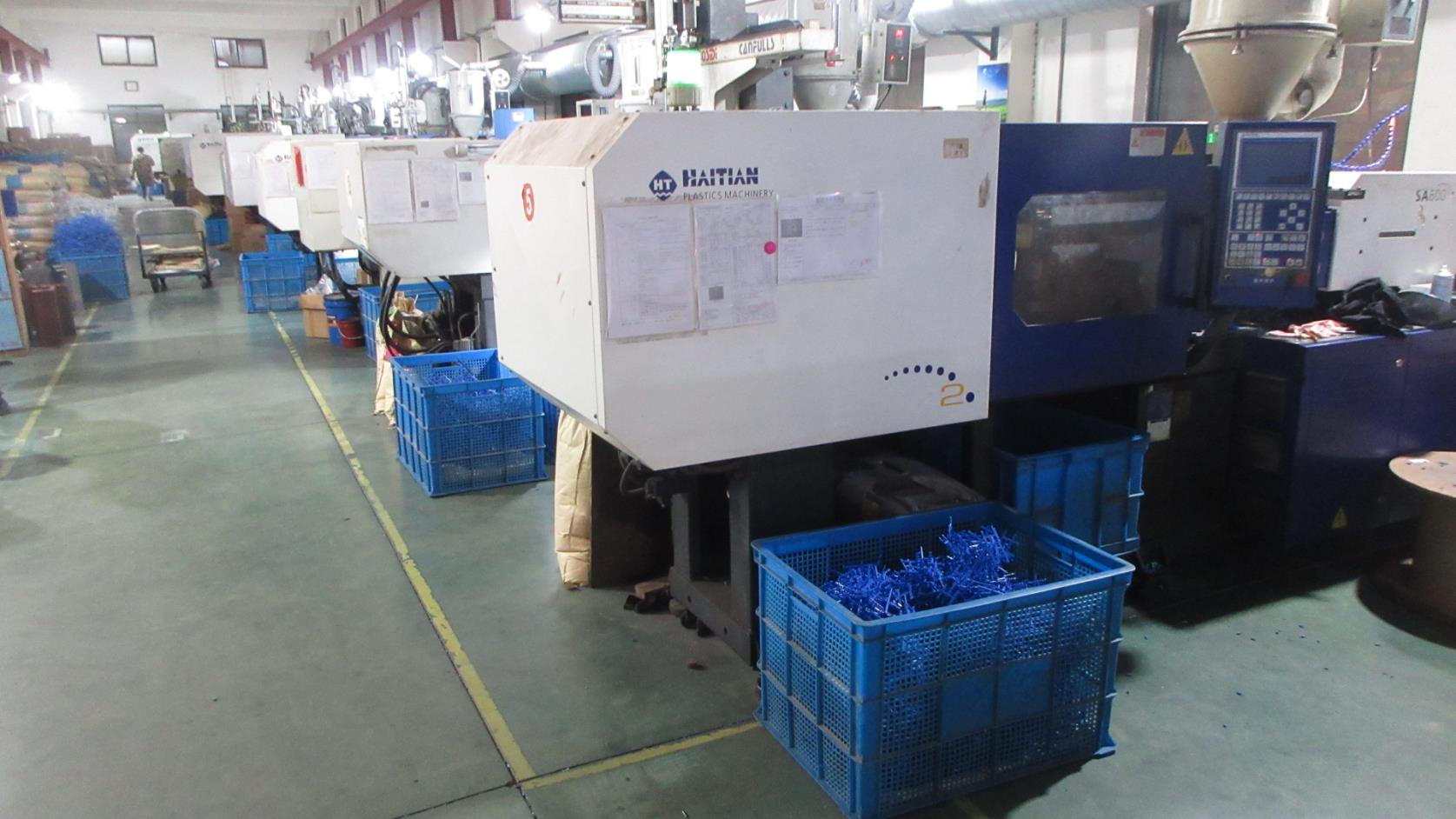
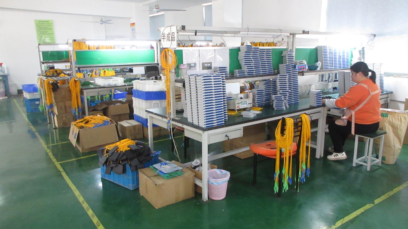
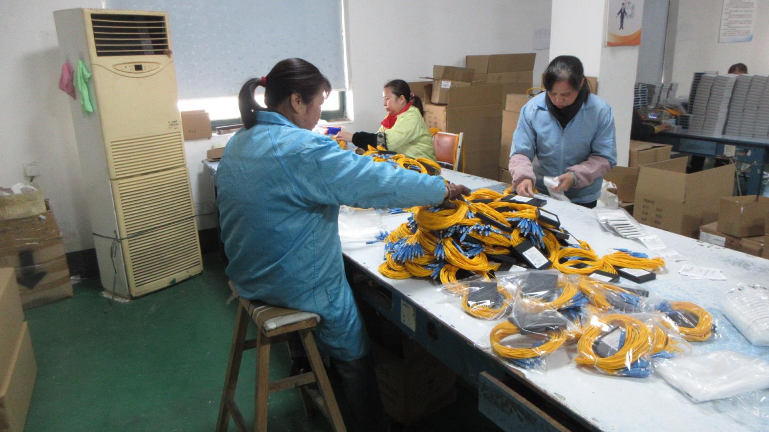

Testing represents the cornerstone of our global reliability strategy. Operating under strict ISO 9001 protocols, Equip-Link verifies every parameters from signal decay to physical stress.
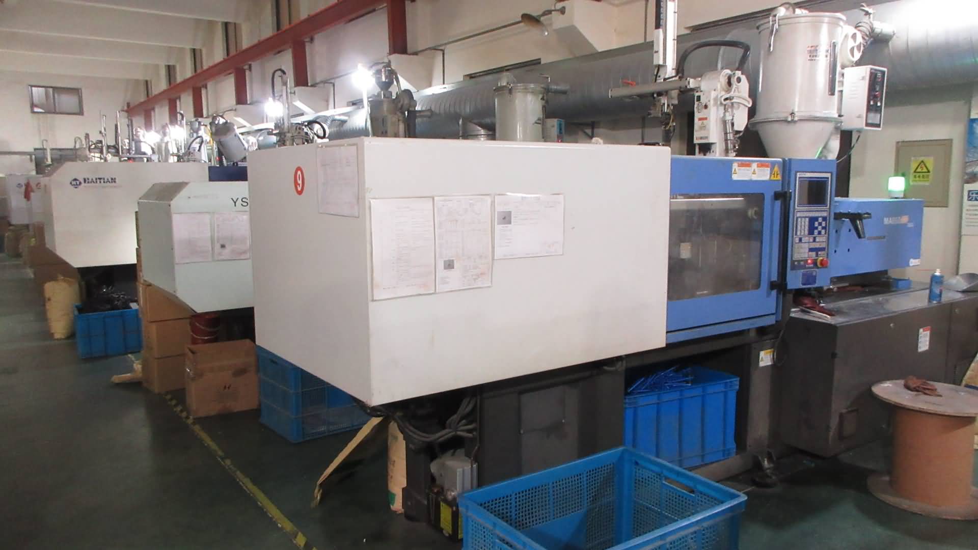
High-accuracy mold injection systems to secure exact mechanical parameters for RJ45 keystones and modular housings.
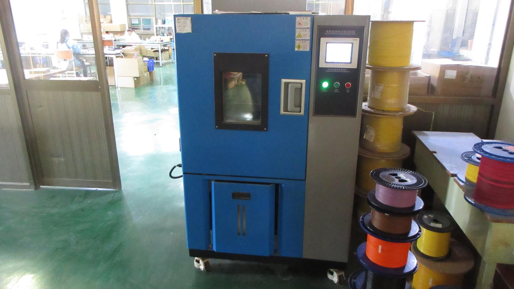
Exposes modules to temperature-humidity cycles to verify component life cycles in industrial networking applications.
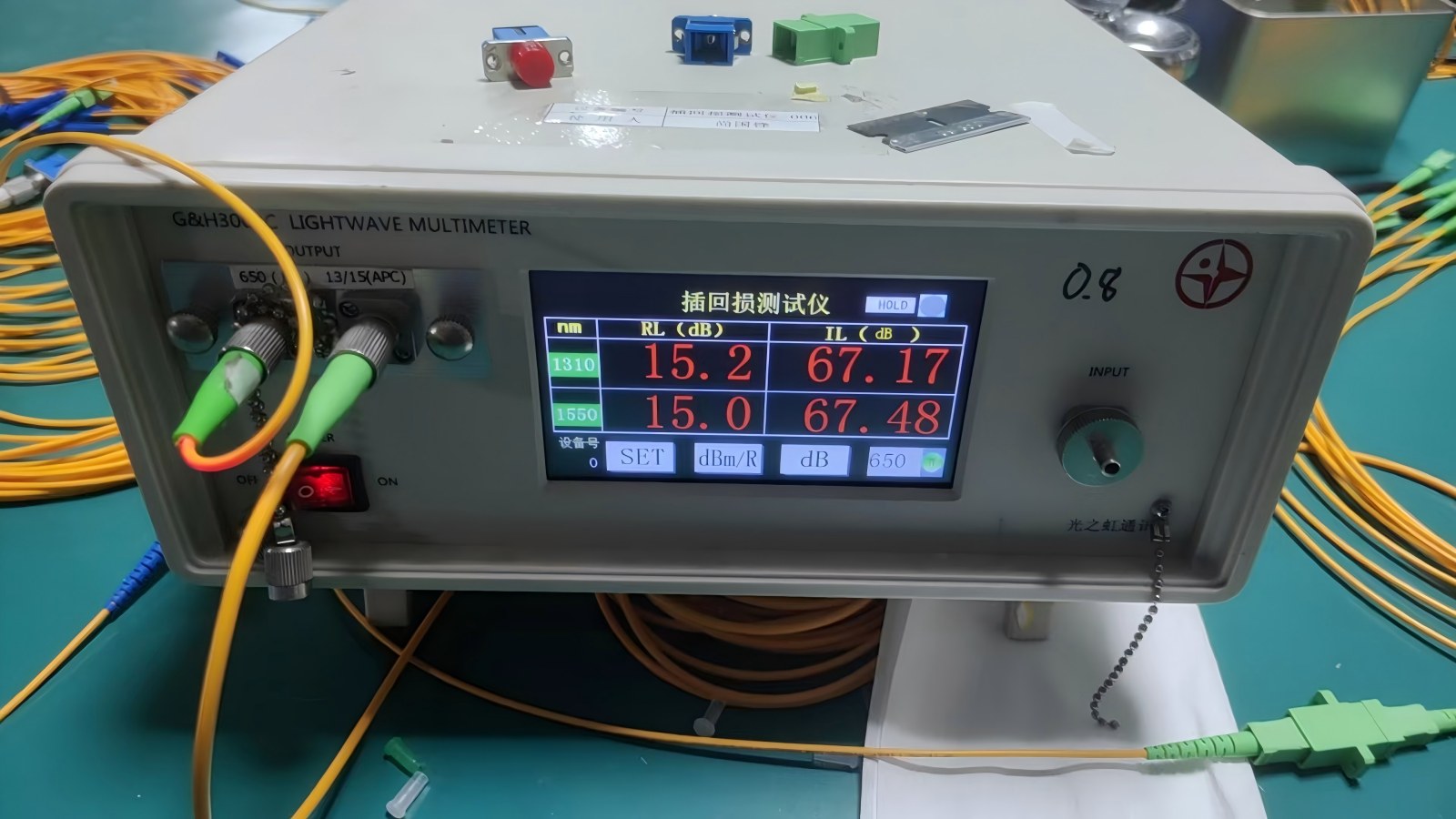
Measures signal attenuation across optical fiber connections to keep performance loss below strict industry limits.
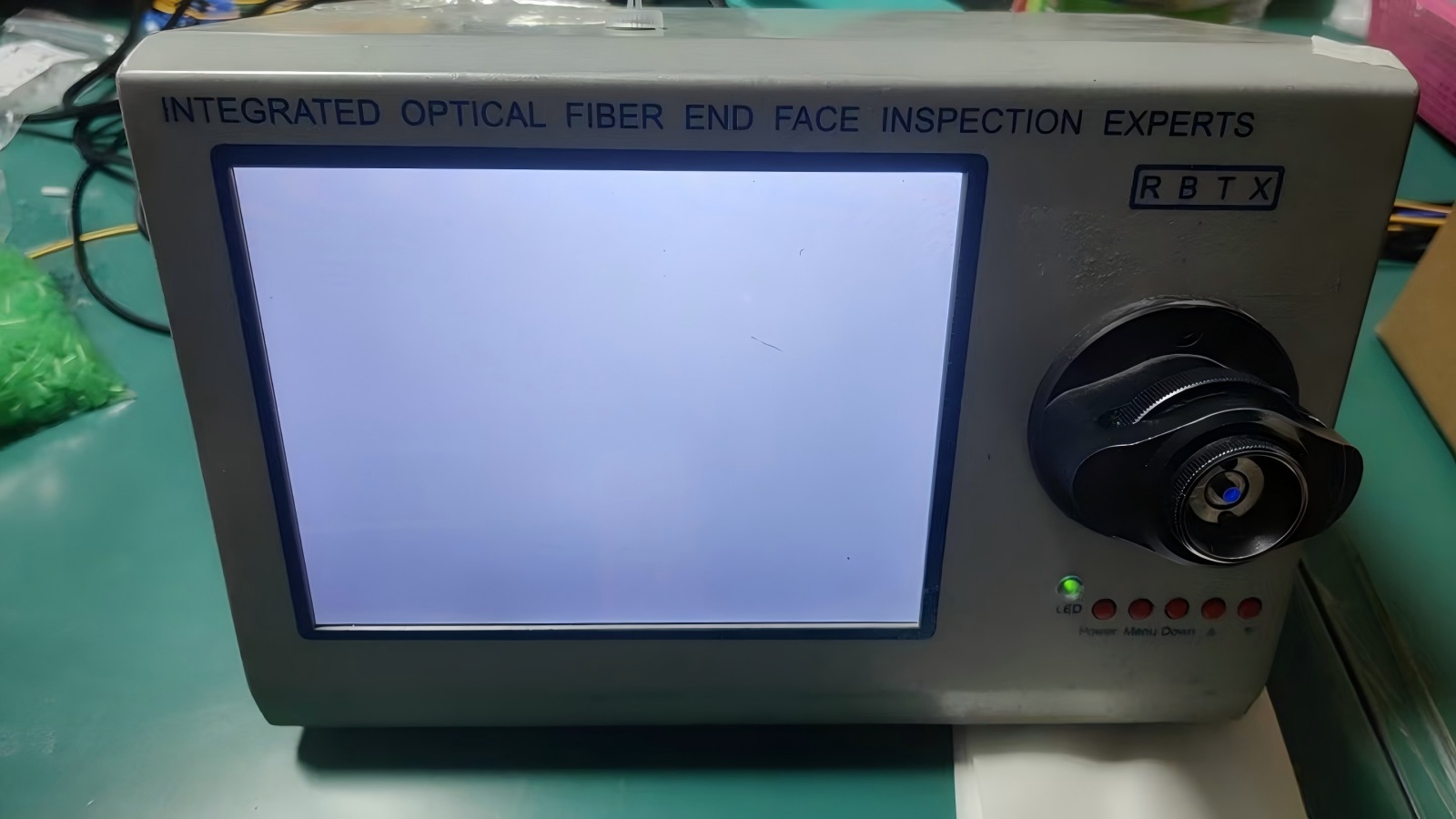
High-magnification visual inspection to confirm optical fiber end-faces are clean and free of physical defects.
Modern procurement teams in North America, Europe, and the Middle East prioritize longevity and standards compliance over simple price points. An unscheduled network link failure can trigger thousands of dollars in lost operating time per minute.
When audit sourcing partners, B2B buyers should evaluate:
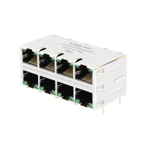
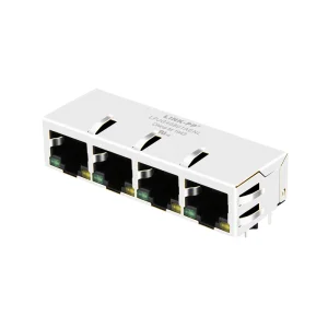
1. High-Density Industrial Hubs: Deploying PoE-enabled RJ45 magnetics and waterproof modular connectors onto factory floors to support automated machinery and telemetry sensors.
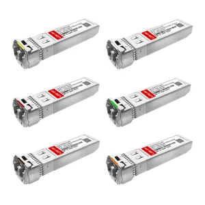
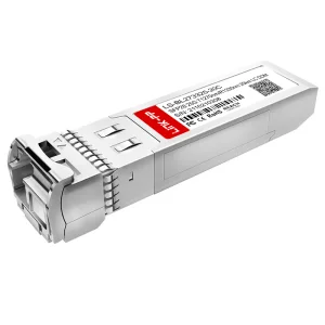
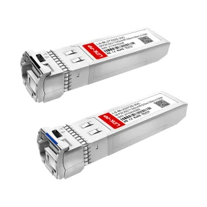
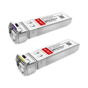
2. Cloud Computing Data Centers: Leveraging single-mode and multi-mode SFP/SFP28 modules and press-fit cages to support fast fiber switching backplanes.
3. Smart Cities & Outdoor CCTV: Deploying IP67-rated waterproof keystone modules to protect critical connections from moisture and extreme weather conditions.
Get answers to key technical questions on physical layout deployment, signal characteristics, and custom OEM manufacturing.
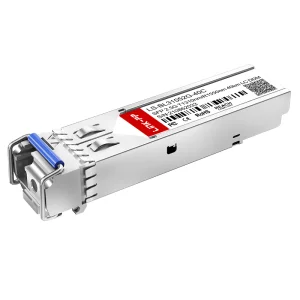
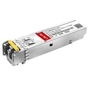
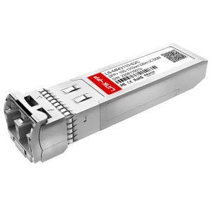
High-performance simplex/duplex transceivers, SFP28 links, and magnetics. Built for modern high-bandwidth cloud networks and core telecom switches.